
0
Owner's of the Makita Cordless Saw Slide Compound Miter Saw gave it a score of 0 out of 5. Here's how the scores stacked up:
[3] DISASSEMBLY/ASSEMBLY
[3]-10. Arm complete, Arm holder (cont.)
DISASSEMBLING
ASSEMBLING
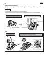
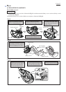
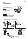
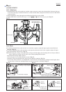
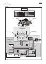
7) Remove CT 4x16 Tapping screw.
Arm holder cover and Position plate can be removed. (Fig. 55)
8) Pull out Center shaft while pushing Leaf spring as illustrated in Fig. 56.
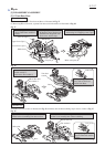
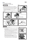
9) After removing Leaf spring from Lock pin 8, pull out Lock pin 8 and
Compression spring 6 in the direction with black arrow. (Fig. 57)
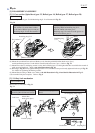
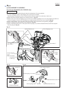
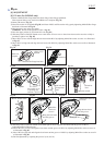
10) Attach a thin slotted screwdriver to Stop ring E-4, and strike the head of
the screwdriver by hand. (Fig. 58)
Stop ring E-4, Cam and Lever 22 section can be removed.
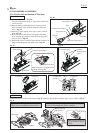
11) Lever 22 section can be separated by removing M4x10 Pan head screw.
(Fig. 59)
Take the disassembling step in reverse.
Note: 1) Leaf spring has to be hooked with the groove of Lock pin 8. (Fig. 56)
2) Do not face the convex of Leaf spring to the opposite of Arm holder
complete. (Fig. 57)
3) Pay attention to the direction of Rod 6. As illustrated in Figs 58 and
59. Tabs on the ends of Stop ring E-4 have to be fit between the
protrusion of Cam and the flat portion of Rod 6. Tab on the center of
Stop ring E-4 has to be fit into the groove of Cam.
4) M10-17 Hex lock nut illustrated in Fig. 52 has to be tighten to 3.5 up
to 4.0N.m. using 1R254, 1R220, 1R222 and Socket assembly 17-38.
When Lever 105 is set in place and Handle is held by hand, Motor
section has to be smoothly tilted without wobbling. Therefore, do fine
adjustment of M10-17 Hex lock nut.
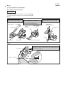
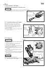
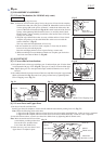
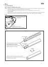
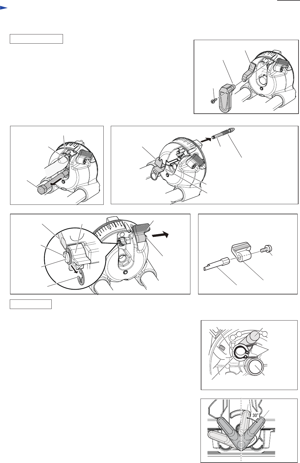
5) One end of Torsion spring 14 has to be hooked with Stopper.
The other of Torsion spring 14 has to be hooked with the center of
Arm holder complete as illustrated in Fig. 60.
6) Lever 105 has to be secured at 0 up to 30 degrees tilted counter-
clockwise (illustrated in light gray color) from the axial-symmetry
position (illustrated in dark gray color) as illustrated in Fig. 61.
Fig. 55
Fig. 56
Fig. 58 Fig. 59
Fig. 60
Flat washer 12
Stopper
Retaining ring S-12
Fig. 61
Fig. 57
P 21/ 37
Repair
CT 4x16
Tapping
screw
Arm holder
cover
Groove of Lock pin 8
Lock pin 8
Lever 22
section
Lever 22
Lever 22 section
Stop ring E-4
M4x10 Pan
head screw
M4x10 Pan
head screw
Slotted screwdriver
Compression spring 6
Arm holder complete
Leaf spring
Center shaft
Position plate
Leaf spring
Cam
Protrusion
of Cam
Rod 6
Rod 6
convex of Leaf spring
center of Arm
holder complete
Torsion
spring 14
Lever 105


Find Your Products By Category
Please Login
