
0
Owner's of the Makita Cordless Saw Slide Compound Miter Saw gave it a score of 0 out of 5. Here's how the scores stacked up:
[3] DISASSEMBLY/ASSEMBLY
[3]-12. Laser Mechanism (for LS1016L only: cont.)
[4] ADJUSTMENT
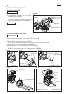
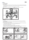
[4]-1. Lower-slide lock mechanism
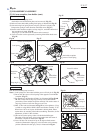
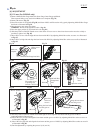
[4]-2. Lower fence and Upper fence
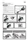
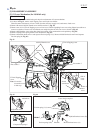
ASSEMBLING
Take the disassembling step in reverse.
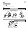
Note: 1) Hook one end of Torsion springs 9(A) to the groove of Laser circuit complete,
and hook the other end to the groove of Block B. Meanwhile, hook one end of
Torsion springs 9(B) to the groove of Block C, and hook the other end to the
groove of Block B as illustrated in Fig. 66. Be careful each end of the Torsion
springs. After tightening M3x6 Pan head screws (A) and (B), check if both
Blocks B and C can be smoothly pivoted due to the reaction force of Torsion
springs 9(A) and 9(B).
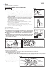
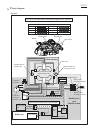
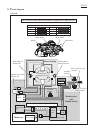
2) Align the top of M4x6 Hex socket set screw with the surface of Laser circuit
complete. Align the top of the other M4x6 Hex socket set screw with the
surface of Block C. (Fig. 67)
This way makes the fine adjustment of Laser easy.
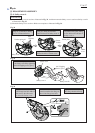
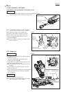
3) Do not touch the lens of Laser circuit complete, or Laser may be unclear
because of dust, dirt and fingerprint.
Dust, dirt and fingerprint have to be wiped off using a cotton swab.
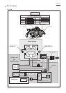
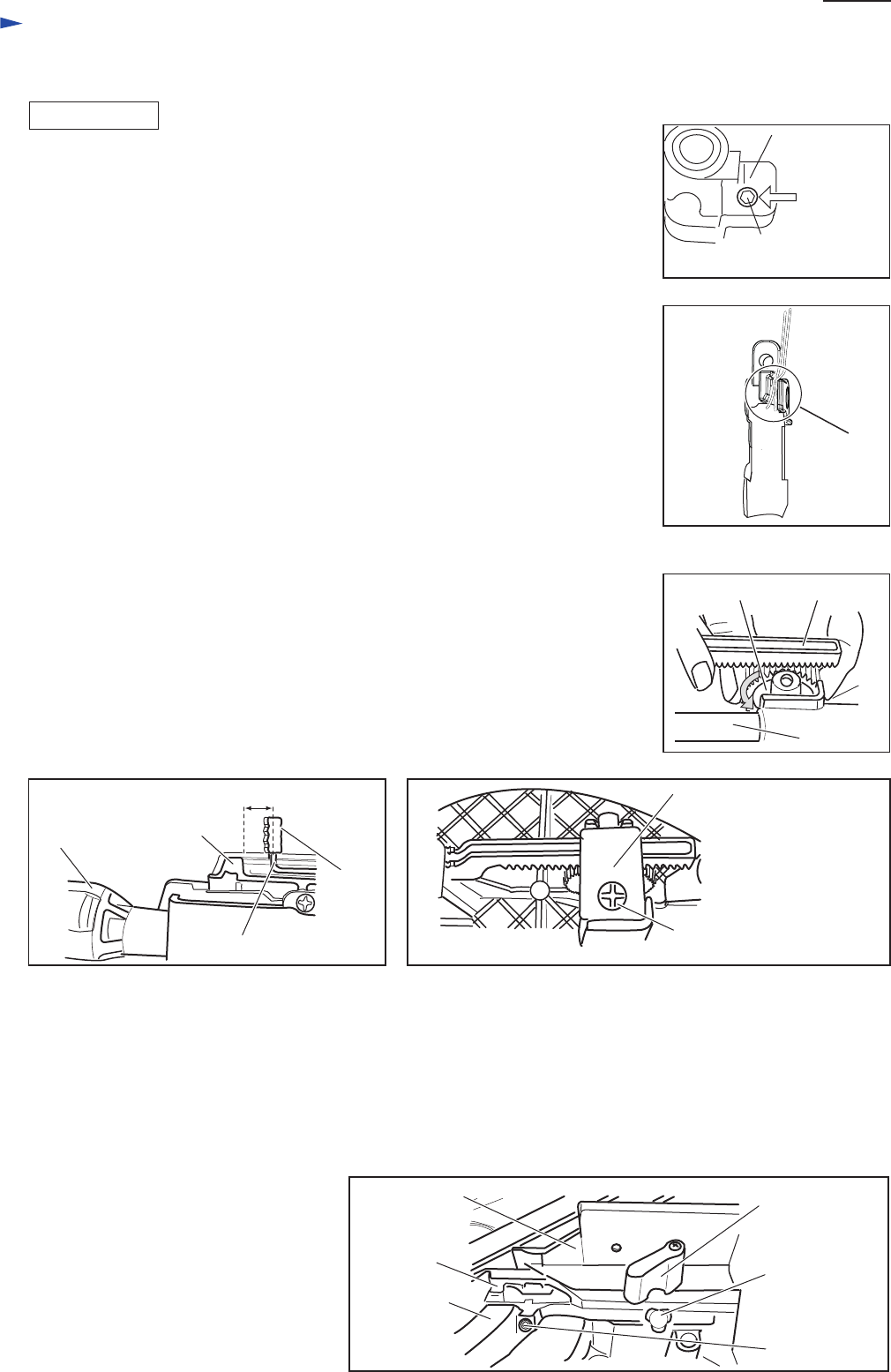
4) When assembling Laser mechanism to Blade case complete, put Lead wires
into Lead wire holder of Block C. (Fig. 68)
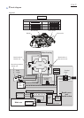
1) Lift up Rack block to disengage with Spur gear 43 and turn Spur gear 43 in the direct
-ion designated with gray arrow. (Fig. 69) Spur gear 43 can be secured to Slide pipe.
Note: Tighten Spur gear 43 to the equivalent torque as M6x18 Thumb screw to Lower
fence R.
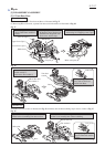
2) On condition that the clearance between Turn base and Slide lock plate is approximate
10mm as illustrated in Fig. 70, secure Leaf spring on Turn base by tightening Bind
CT4x12 Tapping screw. (Fig. 71)
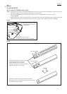
1) Put Lower fence R on Guide fence.
Install Upper fence R complete to Lower fence R and then fasten them by turning Lever 45. (Fig. 72)
Note: Check the following points at this time.
1) Upper fence R complete and Lower fence R can be moved smoothly when M5x6 Hex. socket set screw is loosened.
2) Upper fence R complete and Lower fence R can not be moved when M5x6 Hex. socket set screw is tightened.
2) After check shown above, secure Lower fence R to Guide fence by tightening M6x18 Thumb screw.
Note: Move the outside end of Lower fence
to the farthest possible position from
Base at this time, and then fasten
Lower fence R to Guide fence.
3) In the same way, set Lower fence L and
Upper fence L complete in place.
Fig. 67
P 23/ 37
Repair
Fig. 68
Fig. 69
Fig. 70 Fig. 71
Fig. 72
the surface of
Block C
M4x6 Hex
socket set screw
Lead wire
holder of
Block C
Rack block
Slide pipe
Spur gear 43
approx.10mm Leaf spring
Bind CT4x12 Tapping screw
Turn base
Grip 50
Cap
Slide lock plate
Upper fence R
complete
Lower fence R
Guide fence
M5x6 Hex.
socket set screw
Lever 45
M6x18
Thumb screw


Find Your Products By Category
Please Login
