
0
Owner's of the Makita Router electronic router gave it a score of 0 out of 5. Here's how the scores stacked up:
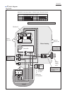
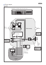
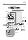
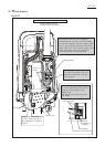
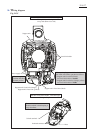
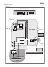
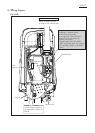
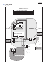
Wiring diagram
RP1801F with electric Brake, LED Job Light
RP1801F with electric Brake, LED Job Light
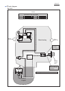
Fig. D-3C
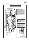
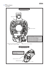
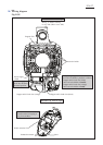
Lead wire holder
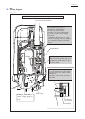
Wiring in Motor housing
on top side (Rear cover side)
Support unit
When putting Support unit’s Lead wires
into Lead wire holders, put them as follows.
* Support unit’s Lead wire (black)
into Lead wire holder of outside
* Support unit’s Lead wires (orange, yellow)
into Lead wire holder of inside
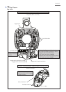
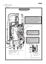
Power supply circuit
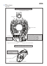
Support unit’s Lead wire (orange)
Support unit’s Lead wire (black)
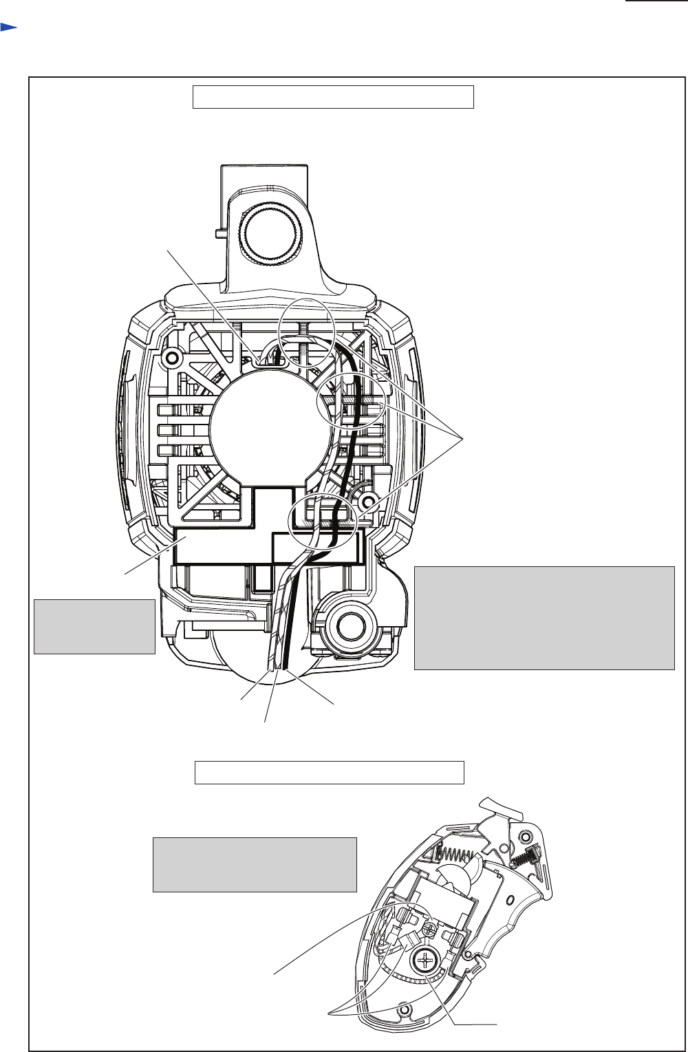
Insulated connector
Wiring in Grip R
Connect Insulated connector to
Switch terminal 2 while keeping it
away from Boss.
Support unit’s Lead wire (yellow)
Put Power supply
circuit into the above
illustrated position.
Switch terminal 2
Boss
P 18/ 27


Find Your Products By Category
Please Login
