
0
Owner's of the Makita Router electronic router gave it a score of 0 out of 5. Here's how the scores stacked up:
[3] DISASSEMBLY/ASSEMBLY
[3]-2. Armature, Motor bracket complete (cont.)
DISASSEMBLING
ASSEMBLING
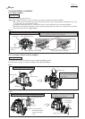
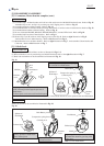
(5) Assemble Grip L to Motor bracket on Lock lever side and secure it with M6x25 Pan head screw. Refer to Fig. 15.
Assemble Grip cover L to Grip L by screwing two 4x12 Tapping screws. Refer to Fig. 15.
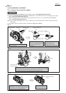
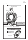
(6) Assemble Armature to Motor bracket. Refer to Fig. 13
(7) Assemble Retainer to Armature shaft by turning with Wrench 41 or Hex socket 41-80 clockwise. Refer to Fig. 12.
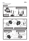
(8) Assemble Motor bracket to Motor housing. Refer to Fig. 11.
(8) In case of Models RP1800F, RP1801F, RP2300F, RP2301FC, connect LED circuit. Refer to Fig. 10.
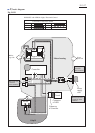
(9) Assemble Grip R section to Motor bracket. Refer to Fig. 9.
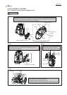
(10) Secure Grip cover (R) with two 4x18 Tapping screws to the Grip R. Refer to right illustration in Fig. 8.
And assemble Cover to Motor housing. Refer to left illustration in Fig. 8.
(11) Mount Retainer cover to Motor bracket. Refer to right illustration in Fig. 7. And assemble Carbon brushes and
Collet nut. Refer to left illustration in Fig. 7.
[3]-3. Shaft Lock
(1) Separate Base section from Motor section as illustrated in Figs. 2, 3.
(2) Remove Retainer cover by unscrewing two M4x18 Pan head screws as the right illustration in Fig. 7.
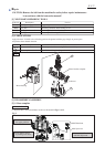
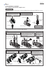
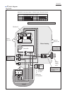
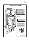
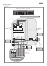
(3) Shaft lock mechanism can be disassembled as illustrated in Fig. 19.
Fig. 19
1R268
Retainer
cover
Applying 1R268 to the pin hole of Push button,
strike Collared pin 6 through the pin hole of
Push button.
Collared pin 6 can be removed from Push button.
Collared pin 6 and Compression spring 8
are removed from Push button.
Push button
Push button
Collared pin 6
Splinter of
Push button
Push button
Compression spring 8
Retainer
cover
Note: The removed Push button has to be replaced with new Push button.
Repair
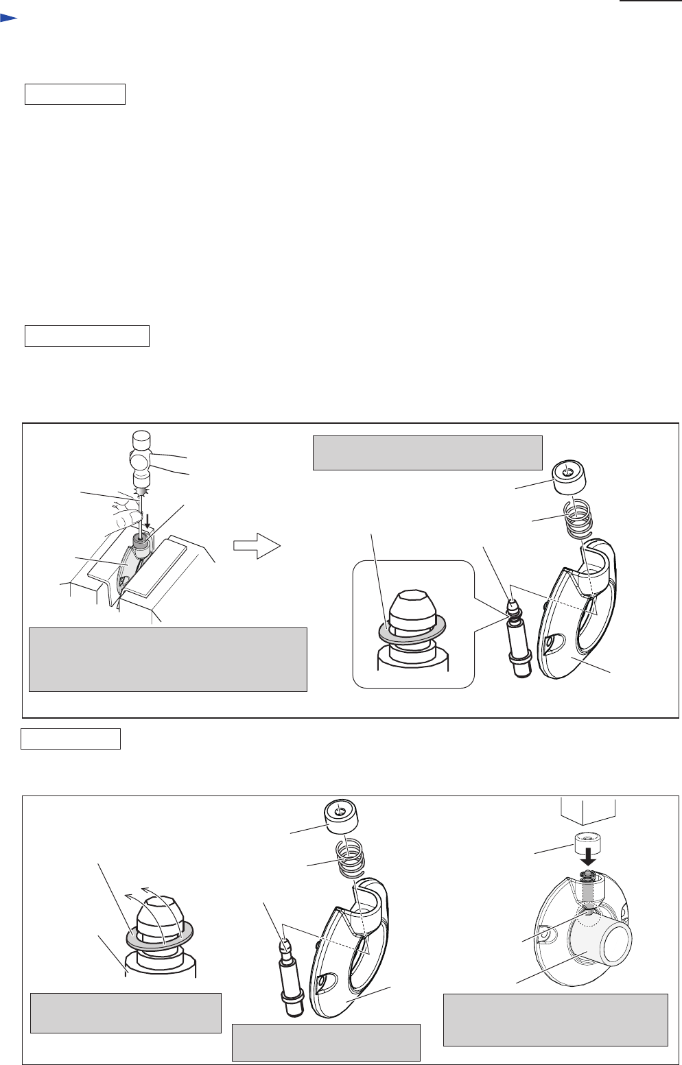
ASSEMBLING
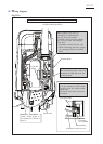
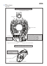
Shaft lock section can be assembled as illustrated in Fig. 20.
Splinter of
Push button
Fig. 20
Push Button
Note: Use new Push button.
Collared pin 6
Collared pin 6
1R030
Collared pin 6
Compression spring 8
Retainer
cover
Remove Splinter of Push button
from Collared pin 6.
Set the parts to Retainer cover
as illustrated above.
Supporting Collared pin 6 with 1R030,
assemble Push button by pressing with
Arbor press.
P 9/ 27


Find Your Products By Category
Please Login
