

0
Owner's of the Black & Decker Grinder Black & Decker Grinder gave it a score of 0 out of 5. Here's how the scores stacked up:
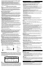

Extension Cord
When using an extension cord, be sure to use one heavy enough to carry the current your
product will draw. An undersized cord will cause a drop in line voltage resulting in loss of
power and overheating. The table below shows the correct size to use depending on cord
length and nameplate ampere rating. If in doubt, use the next heavier gage. The smaller the
gage number, the heavier the cord.
Motor
Your tool is powered by a Black & Decker specified motor. Be sure your power supply agrees
with the nameplate marking. A marking of 120 volts, 50/60 Hz or 120 volts, AC only means
that the tool is designed to operate on normal 120 volt house current. Voltage decrease of
more that 10% will cause loss of power and overheating. All Black & Decker tools are factory
tested. If this tool does not run, check the power supply.
ASSEMBLY
WARNING: To prevent accidental operation, turn off and unplug tool before
performing the following operations. Failure to do this could result in serious
personal injury.
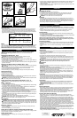
Attaching the Wheel Guard - Fig. 2
WARNING: NEVER GRIND OR BRUSH WITHOUT GUARD IN PLACE.
• Place the tool on a table, with the spindle (9) facing up.
• Place the spring washer (8) over the spindle and locate it on the shoulder (10).
• Place the guard (4) onto the tool as shown.
• Place the flange (7) over the spindle with the protruding pips towards the guard. Make sure
that the holes in the flange align with the screw holes.
• Secure the flange with the screws (6). Make sure that the screws are fully tight and that the
guard can be rotated.
Removing the Wheel Guard (For Sanding Only) - Fig. 3
CAUTION: To prevent loss of control, do not set tool down until accessory has completely
stopped turning.
This tool is fitted with a guard. For sanding only, you can remove the guard as follows:
• Remove the outer flange, disc and inner flange if they have been attached.
• Use a screwdriver to remove the screws (6).
• Remove the flange (7), guard (4) and spring washer (8). Store these parts carefully.
Adjusting the Guard
The guard can be rotated 90°.
• Rotate the guard as required.
Fitting the Side Handle
• A three position auxiliary handle (4) is furnished with your grinder and can be screwed into
either side of the grinder housing as well as into the top.
WARNING: This handle SHOULD BE USED AT ALL TIMES to maintain complete control
of the tool. Always make sure the handle is tight.
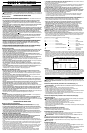
Fitting and Removing Depressed Center Wheels - Fig. 4 - 6
CAUTION: Never use any depressed-center wheels without the proper guard.
Fitting - Figure 4,5
• Fit the guard as described above.
• Place the inner flange (11) onto the spindle (7) as shown (fig. 4). Make sure that the flange
is correctly located on the flat sides of the spindle.
• Place the disc (12) onto the spindle (7) as shown (fig. 4). If the disc has a raised center
(13), make sure that the raised center faces the inner flange.
• Make sure that the disc locates correctly on the inner flange.
• Place the outer flange (14) onto the spindle. When fitting a grinding disc, the raised center
on the outer flange must face towards the disc (A in fig. 5). When fitting a cutting disc, the
raised center on the outer flange must face away from the disc (B in fig. 5).
• Keep the spindle lock (5) depressed and tighten the outer flange using the two-pin spanner
(15) (fig. 6).
• When using a depressed-center wheel, hold the tool so that an angle of approximately 30°
exists between the wheel and the work.
• When using ready-mount or hubbed wheels, flanges are not required.
WARNING: Check rated speed on depressed-center wheel. Never use a wheel with
rated speed lower than the speed on the nameplate of the tool.
EDGE GRINDING
Edge grinding may be done with Type 27 depressed center wheels specifically designed for
this purpose. These wheels are available locally. They must not be subject to side pressure.
CAUTION: Wheels used for edge grinding may break if they bend or twist while being
used for cut-off work or deep grinding. To reduce the risk of serious injury, limit the use of
these wheels to shallow cutting and notching (less than 1/2” in depth). The open side of the
guard must be positioned away from the operator.
Removing - Figure 6
• Keep the spindle lock (5) depressed and loosen the outer flange (14) using the two-pin
spanner (15) (fig. 6).
• Remove the outer flange (14) and the disc (12).
Fitting Wire Cup Brushes & Stringer Bead/Cable Twist Brushes
Wire brushes screw directly on the spindle of the machine without the use of flanges. When
using wire brushes, thread firmly on spindle by hand.
Fitting Abrasive Discs
Use an abrasive disc with a backing pad for sanding with your angle grinder.
• Remove the guard.
Minimum Gage for Cord Sets
Volts Total Length of Cord in Feet
120V 0-25 26-50 51-100 101-150
240V 0-50 51-100 101-200 201-300
Ampere Rating
More Not more American Wire Gage
Than Than
0-6 18 16 16 14
6 - 10 18 16 14 12
10 - 12 16 16 14 12
12 - 16 14 12 Not Recommended
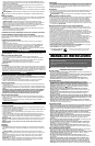
• Place the flange, (backing pad and abrasive disc sold separately) and outer flange on the
spindle as shown in Figure 7. Figure 7A shows how to attach an abrasive disc with a
rubber backing pad.
• Tighten the abrasive disc as shown in Figure 8 by depressing the spindle lock button and
turning the abrasive disc by hand.
OPERATION
WARNING: Let the tool work at its own pace. Do not overload.
Switching On and Off
• To switch the tool on, press the on/off switch (1).
• For continuous operation, press the lock-on button (2) and release the on/off switch.
• To switch the tool off, release the on/off switch. To switch the tool off in continuous
operation, press the on/off switch once more and release it.
WARNING: Do not switch the tool off while under load.
Overload
Overloading will cause damage to the motor of your angle grinder. This can happen if
your angle grinder is subjected to heavy use for prolonged periods of time. Do not in any
circumstances, attempt to exert too much pressure on your angle grinder to speed up
your work. The abrasive discs operate more efficiently when light pressure is exerted,
thus avoiding a drop in the speed of your angle grinder.
SANDING
Precautions to Take When Sanding Paint
• Sanding of lead based paint is NOT RECOMMENDED due to the difficulty of controlling
the contaminated dust. The greatest danger of lead poisoning is to children and pregnant
women.
• Since it is difficult to identify whether or not a paint contains lead without a chemical
analysis, we recommend the following precautions when sanding any paint:
Personal Safety
• No children or pregnant women should enter the work area where the paint sanding is being
done until all cleanup is completed.
• A dustmask or respirator should be worn by all persons entering the work area. The filter should
be replaced daily or whenever the wearer has difficulty breathing.
NOTE: Only those dustmasks suitable for working with lead paint dust and fumes
should be used. Ordinary painting masks do not offer this protection. See your local
hardware dealer for the NIOSH approved proper mask.
Environmental Safety
• Paint should be removed in such a manner as to minimize the amount of dust generated.
• Areas where paint removal is occurring should be sealed with plastic sheeting of 4 mils
thickness.
• Sanding should be done in a manner to reduce tracking of paint dust outside the work
area.
GENERAL INFORMATION
Helpful Hints
• Hold your angle grinder with one hand on the body and the other hand firmly around the
side handle as shown in Figure 9.
• Always position the guard so that as much of the exposed disc as possible is pointing
away from you.
• Be prepared for a stream of sparks when the disc touches the metal.
• Maintain an angle between the disc and work surface (Fig. 10) of approximately 30° when
grinding and 10°-15° when sanding ( Fig. 11) for best tool control, material removal, and
minimal loading.
CAUTION: Use extra care when grinding into a corner as a sudden, sharp movement of
the grinder may be experienced when the wheel contacts a secondary surface.
WARNING: Always wear eye protection while operating this power tool.
Maintenance
Cleaning
Blowing dust and grit out of the motor housing using compressed air is a necessary
maintenance procedure.
CAUTION: Dust and grit from metal grinding often accumulate on interior surfaces and
could create an electrical shock hazard if not cleaned out.
Use only mild soap and a damp cloth to clean the tool. Never let any liquid get inside the
tool; never immerse any part of the tool into a liquid.
IMPORTANT: To assure product SAFETY and RELIABILITY, repairs, maintenance and
adjustment should be performed by authorized service centers or other qualified service
personnel, always using identical replacement parts.
Lubrication
Black & Decker tools are properly lubricated at the factory and are ready for use. Tools
should be lubricated regularly every year depending on usage. (Tools used on heavy duty
jobs and tools exposed to heat may require more frequent lubrication.) This lubrication
should be attempted only by trained power tool repairperson's such as those at Black &
Decker service centers or in other qualified service personnel.
Accessories
Recommended accessories for use with your tool are available from your local dealer or
authorized service center. If you need assistance regarding accessories, please call:
1-800-54-HOW-TO (544-6986).
WARNING: The use of any accessory not recommended for use with this tool could be
hazardous.
Service Information
Black & Decker offers a full network of company-owned and authorized service locations
throughout North America. All Black & Decker Service Centers are staffed with trained
personnel to provide customers with efficient and reliable power tool service.
Whether you need technical advice, repair, or genuine factory replacement parts, contact
the Black & Decker location nearest you. To find your local service location, refer to the
yellow page directory under "Tools—Electric" or call: 1-800-54-HOW TO.
Full Two-Year Home Use Warranty
Black & Decker (U.S.) Inc. warrants this product for two years against any defects in
material or workmanship. The defective product will be replaced or repaired at no charge in
either of two ways.
The first, which will result in exchanges only, is to return the product to the retailer from
whom it was purchased (provided that the store is a participating retailer). Returns should
be made within the time period of the retailer’s policy for exchanges (usually 30 to 90 days
after the sale). Proof of purchase may be required. Please check with the retailer for their
specific return policy regarding returns that are beyond the time set for exchanges.
The second option is to take or send the product (prepaid) to a Black & Decker owned or
authorized Service Center for repair or replacement at our option. Proof of purchase may
be required. Black & Decker owned and authorized Service Centers are listed under "Tools-
Electric" in the yellow pages of the phone directory.
This warranty does not apply to accessories. This warranty gives you specific legal rights
and you may have other rights which vary from province to province. Should you have any
questions, contact the manager of your nearest Black & Decker Service Center. This
product is not intended for commercial use.
FREE WARNING LABEL REPLACEMENT: If your warning labels become illegible or are
missing, call 1-800-544-6986 for a free replacement.
10
11
9
7A
8
See ‘Tools-Electric’
– Yellow Pages –
for Service & Sales
Imported by
Black & Decker (U.S.) Inc.,
701 E. Joppa Rd.
Towson, MD 21286 U.S.A.


Find Your Products By Category
Please Login
