
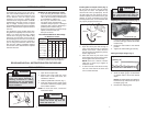
2.9
Owner's of the Milwaukee Drill 5378-20 gave it a score of 2.9 out of 5. Here's how the scores stacked up:
6 7
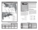
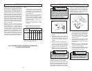
Grounded tools require a three wire exten-
sion cord. Double insulated tools can use
either a two or three wire extension cord.
As the distance from the supply outlet
increases, you must use a heavier gauge
extension cord. Using extension cords with
inadequately sized wire causes a serious
drop in voltage, resulting in loss of power
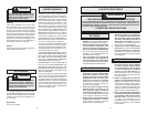
and possible tool damage. Refer to the table
shown to determine the required minimum
wire size.
The smaller the gauge number of the wire,
the greater the capacity of the cord. For ex-
ample, a 14 gauge cord can carry a higher
current than a 16 gauge cord. When using
more than one extension cord to make up
the total length, be sure each cord contains
at least the minimum wire size required. If
you are using one extension cord for more
than one tool, add the nameplate amperes
and use the sum to determine the required
minimum wire size.
Guidelines for Using Extension Cords
• If you are using an extension cord out-
doors, be sure it is marked with the suffi x
“W-A” (“W” in Canada) to indicate that it
is acceptable for outdoor use.
• Be sure your extension cord is prop-
erly wired and in good electrical
condition. Always replace a damaged
extension cord or have it repaired by a
qualifi ed person before using it.
• Protect your extension cords from sharp
objects, excessive heat and
damp or wet areas.
READ AND SAVE ALL INSTRUCTIONS FOR FUTURE USE.
Recommended Minimum Wire Gauge
for Extension Cords*
Extension Cord Length
* Based on limiting the line voltage drop to
fi ve volts at 150% of the rated amperes.
Nameplate
Amperes
0 - 2.0
2.1 - 3.4
3.5 - 5.0
5.1 - 7.0
7.1 - 12.0
12.1 - 16.0
16.1 - 20.0
25'
18
18
18
18
16
14
12
75'
18
18
16
14
12
10
100'
18
16
14
12
10
150'
16
14
12
12
50'
18
18
18
16
14
12
10
EXTENSION CORDS
WARNING
TOOL ASSEMBLY
To reduce the risk of injury, always
unplug tool before attaching or
removing accessories or making
adjustments. Use only specifi cally
recommended accessories. Others
may be hazardous.
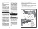
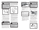
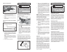
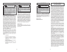
Removing the Chuck (Fig. 1)
1. Open the chuck jaws fully.
2. Remove the screw inside the chuck
head. This is a left hand screw, turn
clockwise to remove.
3. Hold the spindle with a wrench (Fig. 1).
4. Insert the drill chuck key inside chuck
and loosen clockwise by tapping lightly
with a rubber hammer.
NOTE: To mount the chuck, reverse the
instructions above.
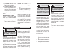
Installing Bits into Keyed Chucks (Fig. 2)
Be sure that the shank of the bit and the
chuck jaws are clean. Dirt particles may
cause the bit to line up improperly. Do not
use bits larger than the maximum recom-
mended capacity of the drill because gear
damage or motor overloading may result.
For best performance, be sure that the bits
are properly sharpened before use.
Fig. 1
Fig. 2
Loosen
Tighten
1. Unplug the tool.
2. Open the chuck jaws wide enough to
insert a bit. Allow the bit to strike the
bottom of the chuck. Center the bit in
the chuck jaws and tighten the jaws by
hand to align the bit.
3. Place the chuck key into each of the
three holes in the chuck, turning it clock-
wise to tighten the chuck securely.
NOTE: Never use a wrench or means
other than a chuck key to tighten or
loosen the chuck.
4. To remove the bit, insert the chuck key
into one of the holes in the chuck and
turn it counterclockwise.
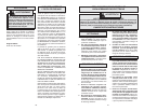
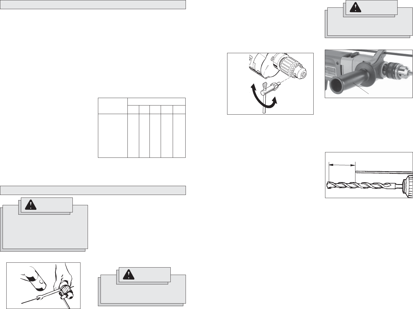
Adjusting the Side Handle Position (Fig. 3)
Fig. 3
Side handle grip
WARNING
To prevent personal injury, always
remove the chuck key from the
chuck after each use.
WARNING
To reduce the risk of injury, always
use a side handle when using this
tool. Always brace or hold securely.
1. Loosen the side handle by unscrewing
the side handle grip until the side handle
rotates freely.
2. Rotate the side handle to the desired
position.
3. Tighten the side handle grip securely.
Setting the Depth Gauge (Fig. 4)
1. Press in the clamping lever.
2. Slide the depth gauge rod backward
or forward until it is set for the desired
depth.
NOTE: The drilling depth is the distance
between the tip of the bit and the tip of
the depth gauge rod.
3. Release the clamping lever.
Fig. 4
Drilling
Depth


Find Your Products By Category
Please Login
