
0
Owner's of the Milwaukee Cordless Drill Milwaukee Cordless Drill gave it a score of 0 out of 5. Here's how the scores stacked up:
4
5
ASSEMBLY
WARNING Recharge only with the
charger specified for the battery. For spe-
cifi c charging instructions, read the operator’s
manual supplied with your charger and battery.
Inserting/Removing the Battery
To remove the battery, push in the release buttons
and pull the battery pack away from the tool.
To insert the battery, slide the pack into the body of
the tool. Make sure it latches securely into place.
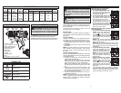
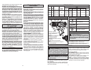
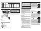
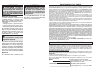
FUNCTIONAL DESCRIPTION
1. Keyless chuck
(Cat. No. 2403-20, 2404-20)
2. Clutch adjusting ring
3. Application selector
4. Speed selector
5. Belt hook
6. Fuel Gauge
7. Trigger
8. Control Switch
9. LED
10.Bit holder (Cat. No. 2402-20)
Cat. No.
Volts
DC
No Load
RPM
No Load
Impacts
per Minute
Capacities
Steel
Wood
MasonryFlat Bit Auger Bit Hole Saw Screws (dia.)
2402-20
2403-20
2404-20
12
12
12
LO 0-450
HI 0-1700
LO 0-450
HI 0-1700
LO 0-450
HI 0-1700
n/a
n/a
LO 6750
HI 25,500
1/4" Hex
1/2"
1/2"
1-1/8"
1-1/8"
1-1/8"
1"
1"
1"
n/a
1-3/4"
1-3/4"
3/8"
3/8"
3/8"
n/a
n/a
3/8"
SPECIFICATIONS
SYMBOLOGY
1
2
6
5
3
4
7
8
9
10
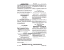
Volts
Direct Current
Impacts per Minute Under
Load (IPM)
No Load Revolutions per
Minute (RPM)
C
US
Underwriters Laboratories, Inc.
United States and Canada
OPERATION
WARNING To reduce the risk of injury,
wear safety goggles or glasses with side
shields.
WARNING Always remove battery
pack before changing or removing acces-
sories. Only use accessories specifically
recommended for this tool. Others may be
hazardous.
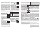
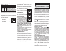
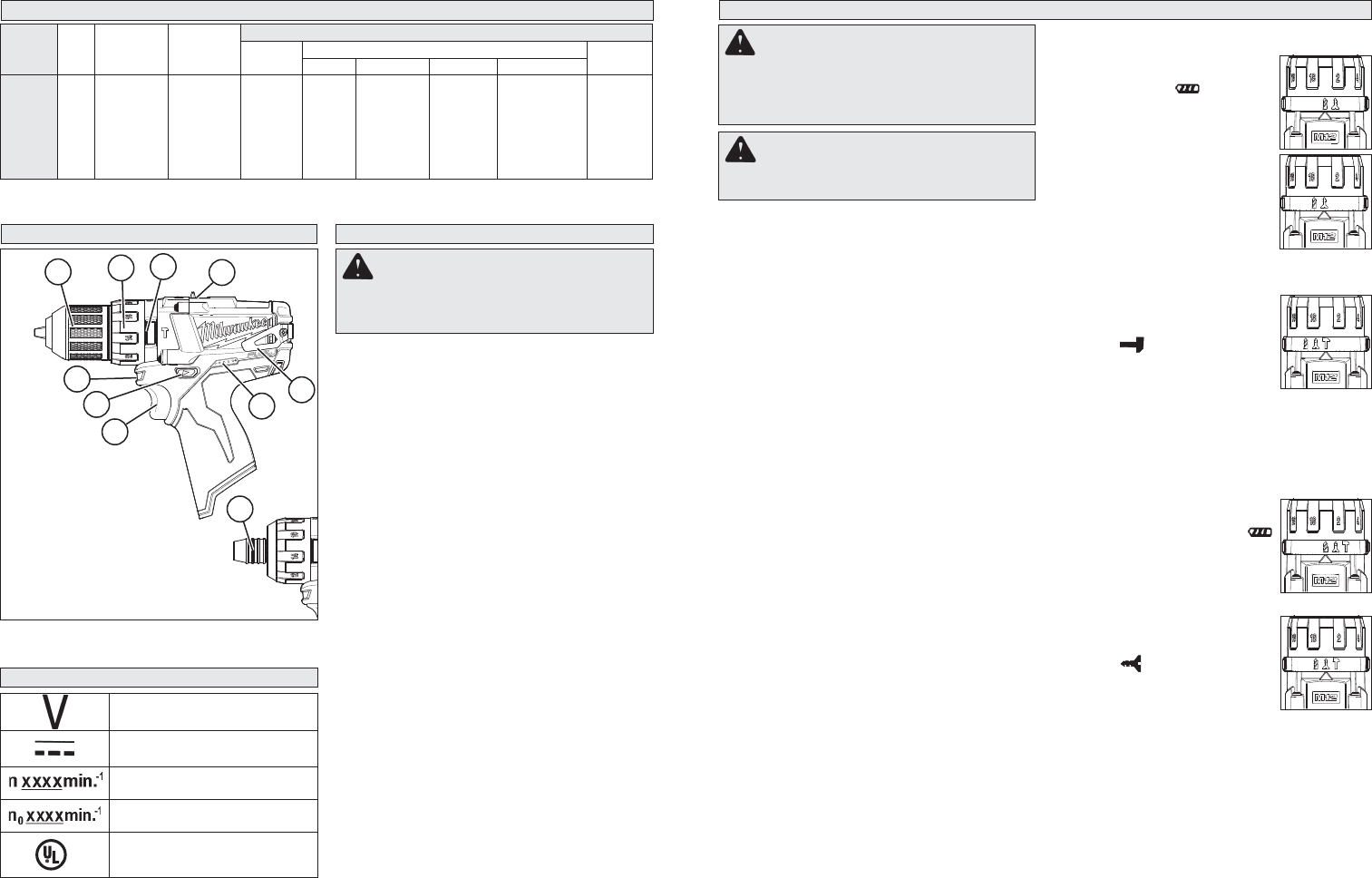
Selecting Drill or Drive Action
(Cat. No. 2402-20, 2403-20)
1. To use the drilling mode, rotate
the torque selector collar until
the drill symbol
appears in
line with the arrow.
2. To use the driving mode rotate
the torque selector collar until
the desired clutch setting ap-
pears in line with the arrow.
The adjustable clutch, when
properly adjusted, will slip at a
preset torque to prevent driving
the screw too deep into different
materials and to prevent dam-
age to the screw or tool.
Selecting Hammer, Drill or Drive Action
(Cat. No. 2404-20)
1. To use the hammer-drilling
mode, rotate the application
selector collar until the hammer
symbol
appears in line with
the arrow. Apply pressure to the
bit to engage the hammering
mechanism.
NOTE: The number selected on the torque
selector collar has no effect on operation of the
drill in hammer mode.
NOTE: When using carbide bits, do not use wa-
ter to settle dust. Do not attempt to drill through
steel reinforcing rods. This will damage the
carbide bits.
2. To use the drilling only mode,
rotate the application selector
collar until the drill symbol
appears in line with the arrow.
NOTE: The number selected on
the torque selector collar has no
effect on operation of the drill in
drilling mode.
3. To use the driving screws
mode rotate the application
selector collar until the drive
symbol
appears in line with
the arrow. Then rotate the torque
selector collar until the desired
clutch setting appears in line with
the arrow.
The adjustable clutch, when properly adjusted,
will slip at a preset torque to prevent driving the
screw too deep into different materials and to
prevent damage to the screw or tool.
Fuel Gauge
To determine the amount of charge left in the bat-
tery, pull the trigger. The Fuel Gauge will light up
for 2-3 seconds.
To signal the end of charge, 1 light on the fuel
gauge will fl ash for 2-3 seconds.
Installing Bits
Always remove the battery before inserting or
removing bits. Select the proper style and size bit
for the job.
Cat. No. 2402-20
This driver is intended for use with drill and driver
bits with a 1/4" hex shank and ball detent recess.
1. To install the bit, press the bit into the socket
until the collar snaps back and the bit is locked
into place.
2. To remove the bit, pull out the collar, then pull
out the bit.
NOTE: It is not necessary to hold the collar out
when installing and removing bits. The fi rst time
the tool is used, it may be necessary to pull out
the collar.
Cat. No. 2403-20, 2404-20
This tool is equipped with a spindle lock. The chuck
can be tightened with one hand, creating higher grip
strengths on the bit.
1. To open the chuck jaws, turn the sleeve in the
counterclockwise direction.
When using drill bits, allow the bit to strike the
bottom of the chuck. Center the bit in the chuck
jaws and lift it about 1/16” off of the bottom.
When using screwdriver bits, insert the bit far
enough for the chuck jaws to grip the hex of the
bit.
2. To close the chuck jaws, turn the sleeve in the
clockwise direction. The bit is secure when the
chuck makes a ratcheting sound and the sleeve
can not be rotated any further.
3. To remove the bit, turn the sleeve in the coun-
terclockwise direction.
NOTE: A ratcheting sound may be heard when the
chuck is opened or closed. This noise is part of the
locking feature, and does not indicate a problem
with the chuck’s operation.


Find Your Products By Category
Please Login
