
0
Owner's of the Milwaukee Impact Driver Milwaukee Impact Wrench gave it a score of 0 out of 5. Here's how the scores stacked up:
4
5
SPECIFIC SAFETY RULES
• When battery pack is not in use, keep it away
from other metal objects like paper clips,
coins, keys, nails, screws, or other small metal
objects that can make a connection from one
terminal to another. Shorting the battery termi-
nals together may cause burns or a fi re.
• Under abusive conditions, liquid may be eject-
ed from the battery; avoid contact. If contact
accidentally occurs, fl ush with water. If liquid
contacts eyes, additionally seek medical help.
Liquid ejected from the battery may cause irritation
or burns.
SERVICE
• Have your power tool serviced by a qualifi ed
repair person using only identical replacement
parts. This will ensure that the safety of the power
tool is maintained.
SYMBOLOGY
Volts
Direct Current
Impacts per Minute Under
Load (IPM)
No Load Revolutions per
Minute (RPM)
Underwriters Laboratories, Inc.
United States and Canada
• Hold power tool by insulated gripping surfaces,
when performing an operation where the fas-
tener may contact hidden wiring. Fasteners
contacting a “live” wire may make exposed metal
parts of the power tool “live” and could give the
operator an electric shock.
• Wear ear protectors when impact drilling.
Exposure to noise can cause hearing loss.
• Use only sockets and other accessories spe-
cifi cally designed for use on impact wrenches
and drivers. Other sockets and accessories might
shatter or break causing injury.
• Maintain labels and nameplates. These carry
important information. If unreadable or missing,
contact a MILWAUKEE service facility for a free
replacement.
• WARNING: Some dust created by power sanding,
sawing, grinding, drilling, and other construction
activities contains chemicals known to cause
cancer, birth defects or other reproductive harm.
Some examples of these chemicals are:
• lead from lead-based paint
• crystalline silica from bricks and cement and other
masonry products, and
• arsenic and chromium from chemically-treated
lumber.
Your risk from these exposures varies, depending
on how often you do this type of work. To reduce
your exposure to these chemicals: work in a well
ventilated area, and work with approved safety
equipment, such as those dust masks that are spe-
cially designed to fi lter out microscopic particles.
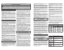
Cat. No.
Volts
DC
RPM IPM
Mode Speed Mode Impacts
2452-20
2453-20
2454-20
12
12
12
1
2
1
2
1
2
0 - 1200
0 - 2650
0 - 1200
0 - 2650
0 - 1200
0 - 2650
1
2
1
2
1
2
0 - 3000
0 - 4000
0 - 2700
0 - 3550
0 - 2650
0 - 3500
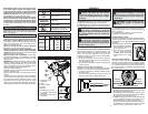
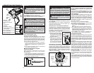
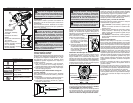
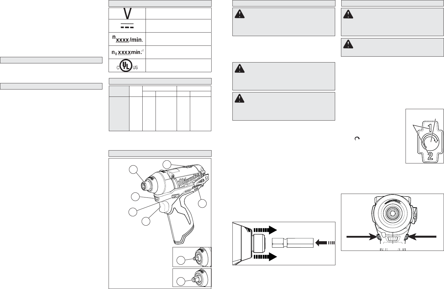
FUNCTIONAL DESCRIPTION
SPECIFICATIONS
1. Hex drive chuck
(2453-20)
2. LED
3. Control switch
4. Trigger
5. Belt clip
6. 2-Mode drive control
7. 1/4” Square drive shank
(2452-20)
8. 3/8” Square drive shank
(2454-20)
1
2
4
3
5
7
8
Fuel Gauge
To determine the amount of charge left in the bat-
tery, pull the trigger. The Fuel Gauge will light up
for 2-3 seconds.
To signal the end of charge, 1 light on the fuel
gauge will fl ash for 2-3 seconds.
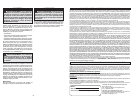
Using the Drive Control
The drive control button is used to adjust the torque,
rotation speed (RPM), and impact speed (IPM) for
the application (see Specifi cations chart for RPM
and IPM).
To select the drive control mode:
1. Pull and release the trigger to
turn on the tool. The current
mode indicator is lit.
2. Press the drive control but-
ton to cycle through the
2 modes. When the desired
mode indiator is lit, begin
work.
Using the Control Switch
The control switch may be set to three positions:
forward, reverse and lock. Due to a lockout mecha-
nism, the control switch can only be adjusted when
the ON/OFF switch is not pressed. Always allow
the motor to come to a complete stop before using
the control switch.
Push for
Forward
Push for
Reverse
PUSH TO CENTER TO LOCK
OPERATION
WARNING Always remove battery
pack before changing or removing
accessories. Only use accessories specifi -
cally recommended for this tool. Others may
be hazardous.
WARNING To reduce the risk of injury,
wear safety goggles or glasses with
side shields.
Attaching and Removing Accessories
Square drive shank (Cat. No. 2452-20, 2454-20)
These impact wrenchs are intended only for use
with sockets designed for impact wrenches that
have a 1/4" (Cat. No. 2452-20) or 3/8" (Cat. No.
2454-20) square drive. Other sockets could shatter
or break, causing injury.
1. To attach a socket or other accessory, align the
accessory with the drive shank and push it fi rmly
over the retaining ring.
2. To remove the accessory, pull the accessory off
the drive shank.
Hex drive chuck (Cat. No. 2453-20)
This driver is intended for use with drill and driver
bits with a 1/4" hex shank and ball detent recess.
1. To attach an accessory, press the shank into the
hex drive chuck.
2. To remove the accessory, pull out the ring and
remove the accessory. Release the ring.
ASSEMBLY
WARNING Recharge only with the
charger specified for the battery.
For specifi c charging instructions, read the
operator’s manual supplied with your charger
and battery.
Inserting/Removing the Battery
To remove the battery, push in the release buttons
and pull the battery pack away from the tool.
To insert the battery, slide the pack into the body of
the tool. Make sure it latches securely into place.
WARNING Use only sockets and other
accessories specifically designed
for use on impact wrenches and drivers.
Other sockets and accessories might shatter
or break causing injury.
WARNING Always remove battery
pack before changing or removing
accessories. Only use accessories specifi -
cally recommended for this tool. Others may
be hazardous.
6
Mode
Indicator
Drive Control
Button
1. For forward (clockwise) rotation, push the
control switch in the direction shown. Check the
direction of rotation before use.
2. For reverse (counterclockwise) rotation, push
the control switch in the direction shown. Check
the direction of rotation before use.
3. To lock the trigger, push the control switch to the
center position. The trigger will not work when
the control switch is in the locked position.
Always remove the battery pack before perform-
ing maintenance, changing accessories, storing
the tool and any time the tool is not in use.


Find Your Products By Category
Please Login
