
0
Owner's of the Milwaukee Yard Vacuum 0884-20 gave it a score of 0 out of 5. Here's how the scores stacked up:
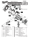
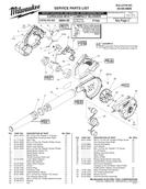
AS AN AID TO REASSEMBLY, TAKE
NOTICE OF WIRE ROUTING AND
POSITION IN WIRE GUIDES AND
TRAPS WHILE DISMANTLING TOOL.
BE CAREFUL AND AVOID PINCHING
WIRES BETWEEN HANDLE HALVES
WHEN ASSEMBLING.
= WIRE TRAPS
or GUIDES
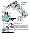
On-Off Switch
Main PCBA
Motor
Battery Terminal
Block
Switch PCBA
#13 Lower
Motor Support
#15 Upper
Motor Support
#14 Motor
#2 Handle/Motor
Housing Halve
Channel in
Lower Motor
Support for
red motor wire
Channel in Lower Motor
Support for black motor wire
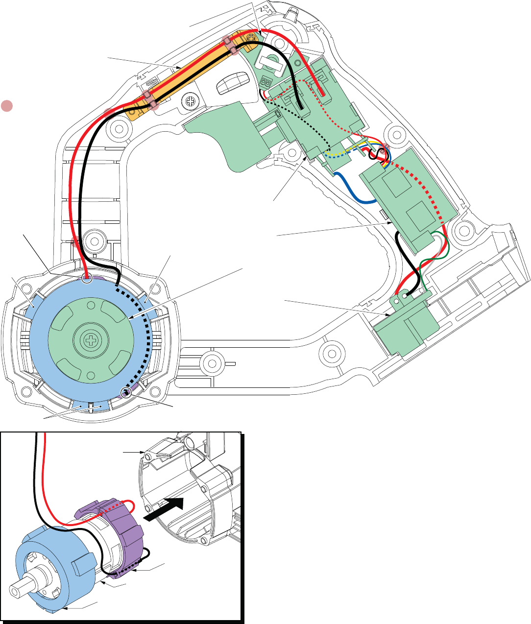
When reinstalling a new Motor Assembly, be sure that the red and black motor
leads are fed through the large opening in the back of the Lower Motor Support
before soldering wires to the On-Off Switch.
Slide the lower motor support onto the rear of the motor, orienting it as shown
and making sure it is firmly pressed into place.
Be sure that the Upper Motor Support is oriented as shown and firmly seated on
the spindle end of the Motor.
Press the motor leads into the channels of the lower motor support and remove
most of the slack from the rear of the motor. Line up the rubber lugs of the upper
and lower motor supports with the channels in the motor cavity of the Handle/
Motor Housing Halve. Install the assembly into the handle/motor housing halve.
NOTE:
For ease of installation, the upper motor support can be left off the spindle end
of the motor until the lower motor support and motor are pressed into place. At
that time, the upper motor support can be assembled onto the motor, orienting
the rubber lugs with the corresponding channels in the motor cavity and firmly
seated.
Rubber lugs
Rubber lugs
Rubber
lugs
Wire Trap #3


Find Your Products By Category
Please Login
