
0
Owner's of the Black & Decker Grinder 5.5A 4-1/2" GRINDER gave it a score of 0 out of 5. Here's how the scores stacked up:

7
ASSEMBLY
WARNING:
To prevent accidental
operation, turn off and unplug tool before
performing the following operations.
Failure to do this could result in serious
personal injury.
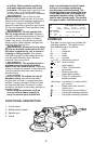
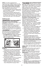
AUXILIARY HANDLE
WARNING: This handle SHOULD
BE USED AT ALL TIMES to maintain
complete control of the tool.
An auxiliary 3 position handle is furnished
with your grinder. It can be screwed into
either side or the top of the gear case
housing. This handle SHOULD BE USED
AT ALL TIMES to maintain complete
control of the tool.
MOUNTING GUARD
The guard must be used with all grinding
wheels, sanding flap discs, wire brushes,
cut-off wheels and wire wheels. The tool
may be used without a guard only when
sanding with conventional sanding discs.
intended for use with most depressed
guard is designed for use with sanding
brushes. Never use Type 1 cutting discs
Grinding and cutting with wheels other
accessory guards.
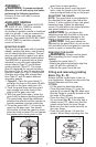
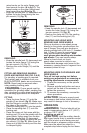
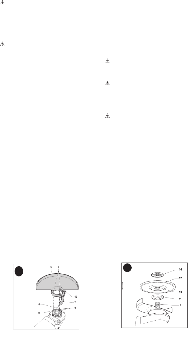
1. Figure A - Open the guard latch (7),
and align the lugs on the guard (8) with
the slots on the gear case cover (9).
lugs engage and rotate freely in the
groove on the gear case hub.
3. With the guard latch open, rotate the
guard into the desired working position.
The guard body should be positioned
between the spindle and the operator to
provide maximum operator protection.
4. Close the guard latch (7) to secure the
guard on the gear case. You should
not be able to rotate the guard by hand
when the latch is closed. Do not operate
the grinder with a loose guard or the
guard latch in open position.
latch, rotate the guard so that the lugs and
slots are aligned and pull up on the guard.
ADJUSTING THE GUARD
NOTE: The guard latch is pre-adjusted to
the diameter of the gear case hub at the
factory. If, after a period of time, the guard
becomes loose, tighten the adjusting
and guard installed on the tool.
CAUTION: Do not tighten the
adjusting screw with the latch in the open
position. Undetectable damage to the
guard or the mounting hub may result.
CAUTION: If the guard cannot be
tightened by the guard latch, do not use the
tool and take the tool and guard to a service
center to repair or replace the guard.
REMOVING THE GUARD
WARNING: Always use the guard
when operating the tool, except when
sanding.
lugs (8) with the notches (9).
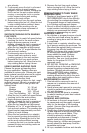
Fitting and removing grinding
discs (fig. B - D)
Always use the correct type of disc for
your application. Always use discs with the
correct diameter and bore size.
FITTING
(fig. B). Make sure
that the flange is correctly located on the
flat sides of the spindle.
(fig. B). If the disc has a
raised center (13), make sure that the
raised center faces the inner flange.
the inner flange.
spindle. When fitting a grinding disc, the
A
B


Find Your Products By Category
Please Login
