

0
Owner's of the Black & Decker Grinder 5.5A 4-1/2" GRINDER gave it a score of 0 out of 5. Here's how the scores stacked up:

8
E
D
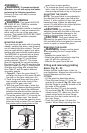
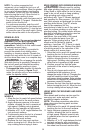
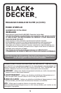
raised center on the outer flange must
face towards the disc (A in fig. C). The
raised center on the outer flange must
face toward the disc (B in fig. C).
tighten the outer flange using the two-
(fig. D).
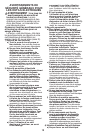
REMOVING
loosen the outer flange (14) using the
disc (11).
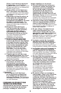
FITTING AND REMOVING SANDING
DISCS AND BACKING PAD (FIG. D & E)
For sanding, a backing pad is required.
The backing pad is available from your
dealer as an accessory.
NOTE: Guard may be removed when
using sanding backing pads.
WARNING: Proper guard must be
reinstalled for grinding wheel, sanding flap
disc, wire brush or wire wheel applications
after sanding applications are complete.
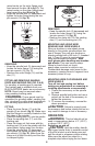
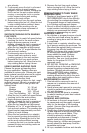
FITTING
(fig. E). Make sure
that the flange is correctly located on the
flat sides of the spindle.
backing pad.
backing pad (14) onto the spindle with the
raised center facing away from the disc.
and tighten the clamp nut using the two-
(fig. D). Make sure the
clamp nut is fitted correctly and the disc
is clamped tightly.
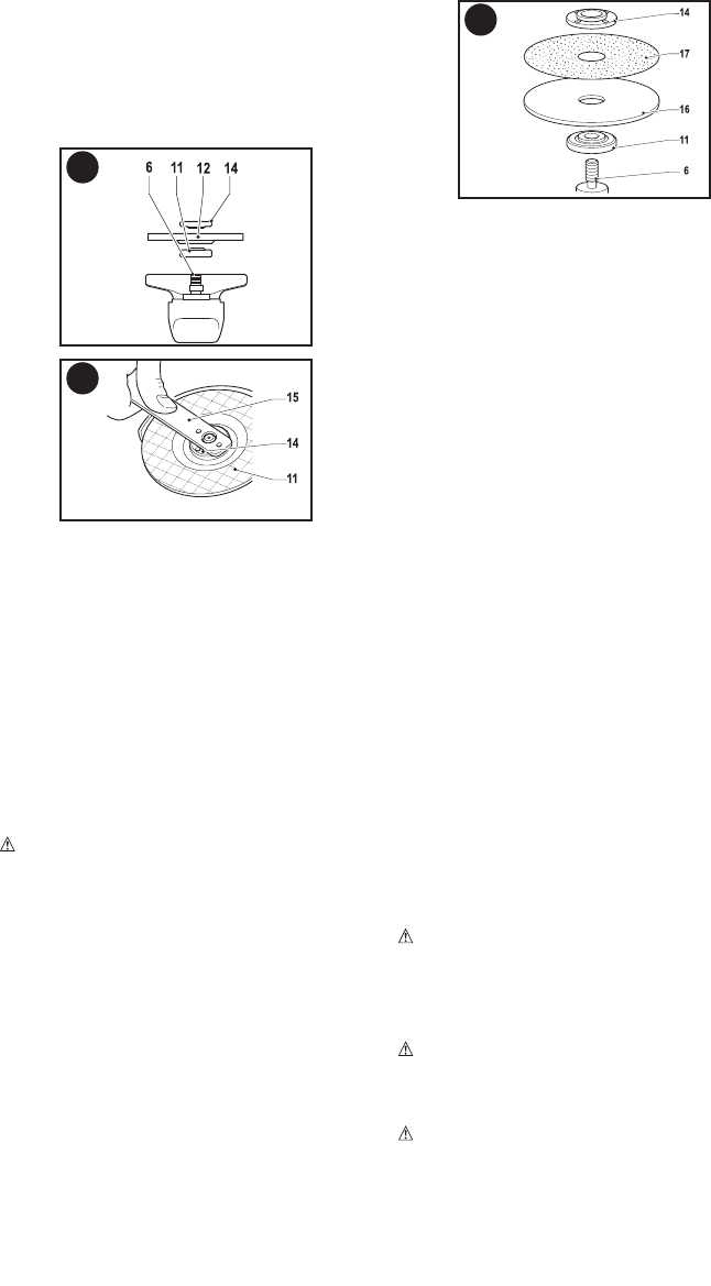
REMOVING
loosen the outer flange (14) using the
(fig. D).
MOUNTING AND USING WIRE
BRUSHES AND WIRE WHEELS
Wire cup brushes or wire wheels screw
directly on the grinder spindle without the
use of flanges. Use only wire brushes or
using wire brushes and wheels. Wear
work gloves when handling wire brushes
and wheels. They can become sharp.
Wheel or brush must not touch
guard when mounted or while in use.
Undetectable damage could occur to the
accessory, causing wires to fragment from
accessory wheel or cup.
MOUNTING WIRE CUP BRUSHES AND
WIRE WHEELS
Turn off tool and unplug tool before
making any adjustments or removing or
installing attachments or accessories.
1. Thread the accessory on the spindle
by hand.
wrench on the hub of the
accessory
to
tighten the
accessory
.
3. To remove the
accessory
, reverse the
above procedure.
CAUTION:
Failure to properly seat
the
accessory
hub before turning the tool on
may result in damage to tool or
accessory
.
OPERATION
WARNING:
This tool should not be
Switching on and off
CAUTION: Hold the auxiliary handle
and trigger handle
firmly to maintain control
of the tool at start up and during use and
until the wheel or accessory stops rotating.
Make sure the wheel has come to a
complete stop be fore laying the tool down.
C


Find Your Products By Category
Please Login
