

0
Owner's of the Black & Decker Lawn Mower Black & Decker MAX 20V 10" Compact Cordless String Trimmer/Edger gave it a score of 0 out of 5. Here's how the scores stacked up:


6
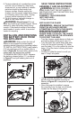
5. Foreign materials of a conductive nature
such as, but not limited to, steel wool,
aluminum foil, or any buildup of metallic
particles should be kept away from
charger cavities. Always unplug the
charger from the power supply when there
is no battery pack in the cavity. Unplug
charger before attempting to clean.
6. Do not freeze or immerse charger in
water or any other liquid.
WARNING: Shock hazard. Do not
allow any liquid to get inside charger. Never
attempt to open the battery pack for any
reason. If the plastic housing of the battery
pack breaks or cracks, return to a service
center for recycling.
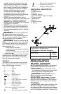
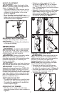
INSTALLING AND REMOVING
THE BATTERY PACK FROM
THE APPLIANCE
WARNING: Make certain the lock-off
button is not engaged to prevent switch
actuation before removing or installing battery.
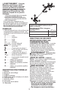
TO INSTALL BATTERY PACK: Insert battery
(10) into appliance until an audible click is
heard (Figure B). Ensure battery pack is fully
seated and fully latched into position.
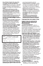
TO REMOVE BATTERY PACK: Depress
the battery release button (11) as shown
in Figure C and pull battery pack out of
appliance.
B
10
C
11
SAVE THESE INSTRUCTIONS
ASSEMBLY AND ADJUSTMENT
WARNING: BEFORE ASSEMBLY,
MAKE SURE THAT THE APPLIANCE IS
SWITCHED OFF AND THE BATTERY HAS
BEEN REMOVED.
ASSEMBLY TOOLS REQUIRED
(NOT SUPPLIED):
- Phillips Screwdriver
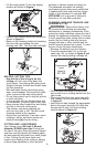
INSTALLING THE GUARD
WARNING: REMOVE THE BATTERY
FROM THE APPLIANCE BEFORE
ATTEMPTING TO ATTACH THE GUARD,
EDGE GUIDE OR HANDLE. NEVER
OPERATE APPLIANCE WITHOUT
GUARD FIRMLY IN PLACE. THE GUARD
MUST ALWAYS BE ON THE APPLIANCE
TO PROTECT THE USER.
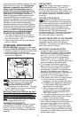
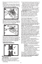
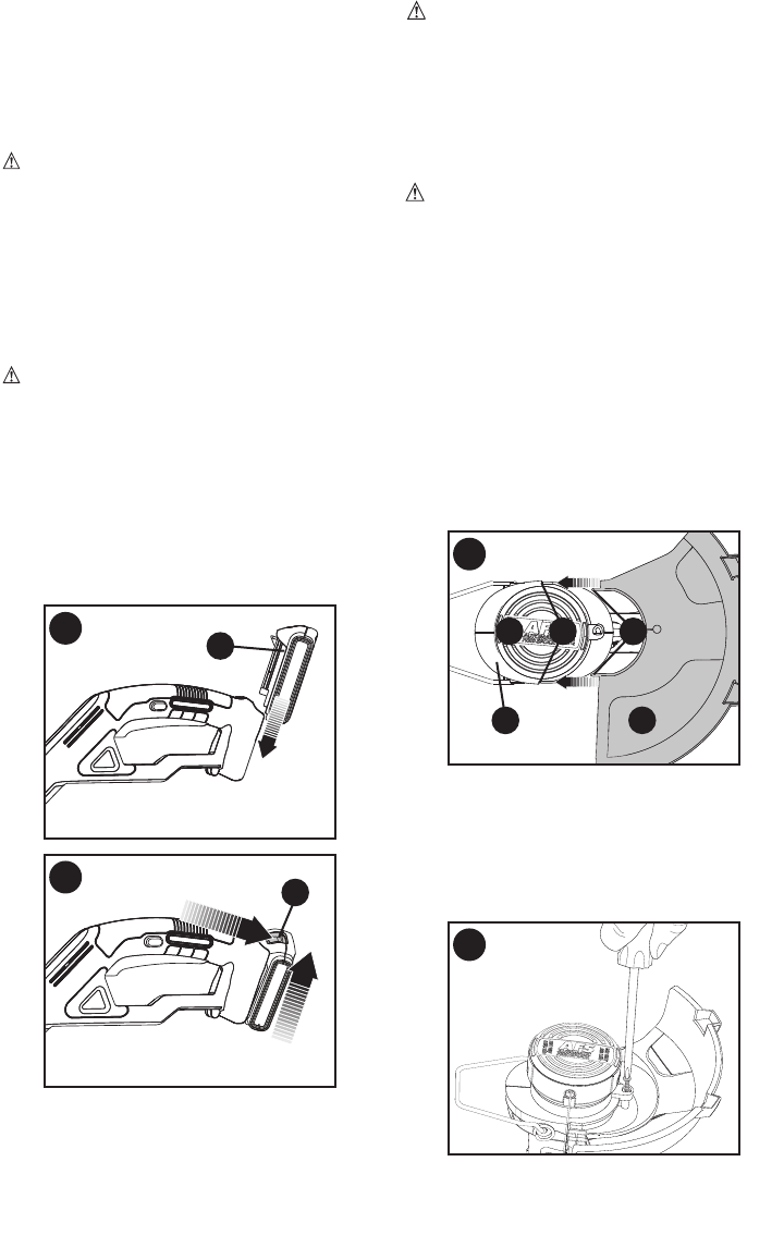
• Turn the trimmer upside down so that you
are looking down at the spool cap (11).
• Turn the guard (8) upside down and slide
it fully into the motor housing (12). Make
sure the tabs (13) on the guard slip into the
holes (14) of the motor housing as shown
in Figure D.
• Continue to slide the guard on until you
hear it “snap” into place.
D
11
8
12
13
14
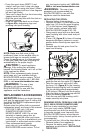
• Using a phillips screwdriver, insert the
guard screw and tighten securely as
shown in Figure E to complete the guard
assembly.
• Once the guard is installed, remove
the covering from the line cut-off blade,
located on the edge of the guard
E


Find Your Products By Category
Please Login
