
4.1
Owner's of the Broan Fan 164 gave it a score of 4.1 out of 5. Here's how the scores stacked up:
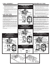
FINAL ASSEMBLY
1. Protect motor, bulb sockets and wiring from con-
struction dust, drywall spray, paint, etc. by using
the plaster shield. Cut it from the carton and fol-
low directions printed on it. (Fig. 7)
2. Finish all ceiling work as necessary.
3. Remove plaster shield and check if bottom of
housing is flush with finished ceiling. If not, loosen
vertical adjusting screws, reposition housing, and
retighten screws.
4. Attach grille by hooking springs onto clips on side
of housing. (Fig. 8)
5. Install BR40 or R40-size 250W infrared bulb(s).
Center grille around bulb(s).
USE AND CARE
MODELS 162 & 164 OPERATION NOTE: These units
are designed with a thermostat which senses excess
heat and may start the blower automatically. This is
normal and is no cause for concern.
DISCONNECT ELECTRIC POWER SUPPLY AND
LOCK OUT SERVICE PANEL BEFORE CLEANING
OR SERVICING THIS UNIT.
To clean fan assembly: Remove bulb(s). Unhook
springs and remove grille. Loosen motor assembly
mounting screws and rotate assembly to remove it
from housing. Gently vacuum fan, motor and interior
of housing. Reverse steps to replace fan assembly.
To clean grille assembly: Remove bulb(s). Unhook
springs and remove grille. Clean grille with mild soapy
water. Use a mild detergent, such as dishwashing liq-
uid. Dry with a soft cloth. DO NOT USE ABRASIVE
CLOTHS, STEEL WOOL PADS OR SCOURING POW-
DERS.
Motor is permanently lubricated — Do not oil or dis-
assemble motor.
ENSAMBLADO FINAL
1. Proteja el motor, enchufe de la bombilla y cableado
contra el polvo de la construcción, rocíos de yeso,
pintura, etc., usando el escudo de yeso. Córtelo de
la caja de cartón y siga las instrucciones que apare-
cen impresas en la misma. (Fig. 7)
2. Termine el trabajo de cielo raso ségun se necesite.
3. Quite el escudo de yeso y verifique si la parte inferior
de la caja está a nivel con el cielo raso terminado. De
lo contrario, afloje los tornillos de ajuste vertical, cam-
bie la posición de la caja y vuelva a apretar los torni-
llos.
4. Fije la rejilla enganchando los resortes a los
sujetadores al costado de la caja. (Fig. 8)
5. Instale bombilla(s) infrarrojas 250W de tamaño BR40
o R40. Centre la rejilla alrededor de la(s) bombilla(s).
USO Y MANTENIMIENTO
INSTRUCCIONES SOBRE EL FUNCIONAMIENTO DEL
MODELOS 162 Y 164: Estas unidads ha sido diseñada
con un termostato que detecta los excesos de calor y
puede encender el soplador automáticamente. Esto es
normal y no debe ser motivo de preocupación.
DESCONECTE EL SUMINISTRO DE ENERGIA ELEC-
TRICA Y ASEGURE EL PANEL DE SERVICIO ANTES
DE LIMPIAR O DAR SERVICIO A ESTA UNIDAD.
Para limpiar el equipo de ventilador: quite la(s)
bombilla(s). Desenganche los resortes y quite la rejilla.
Afloje los tornillos de montaje del equipo del motor y gire
el equipo para sacarlo de la caja. Limpie por aspiración el
ventilador, motor e interior de la caja. Proceda al revés
para reemplazar el equipo del ventilador.
Para limpiar el equipo de la rejilla: quite la(s) bombilla(s).
Desenganche los resortes y saque la rejilla. Limpie la re-
jilla con agua enjabonada. Use un detergente suave, como
por ejemplo líquido de lavado de platos. Seque con un
paño liviano. NO USE PAÑOS ÁSPEROS, LANA DE ACE-
RO O POLVOS DE FREGADO.
El motor está lubricado en forma permanente. No aceite
ni desarme el motor.
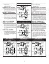
FIG. 6 (CONT')
3
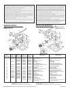
MODEL / MODELO 164
Vent & Heat operate together -
Light separately
El Ventilador y Calentador funcionan a la vez
-La Luz por separado
MODEL / MODELO 164
Lamps operate together -
Vent separately
Las Lamparas funcionan a la vez -
El ventilador por separado
120 VAC LINE IN
LINEA DE ENTRADA 120 VCA
GROUND
TIERRA
LIGHT
LUZ
DUAL CONTROL
CONTROLE DE 2 FUNCCIONES
3 WHITE / GRAY WIRES
3 ALAMBRES
BLANCO / GRIS
VENT & HEAT
VENTILADOR y
CALEFACCION
BLACK to BLACK,
& YELLOW
NEGRO a
NEGRO
y AMARILLO
RED to RED
& BLUE
ROJO a ROJO
y AZUL
GROUND / TIERRA
RED
ROJO
WHITE to
WHITE
BLANCO a
BLANCO
BLACK
NEGRO
120 VAC LINE IN
LINEA DE ENTRADA 120 VCA
GROUND
TIERRA
VENT
VENTILADOR
DUAL CONTROL
CONTROLE DE 2 FUNCCIONES
3 WHITE / GRAY WIRES
3 ALAMBRES
BLANCO / GRIS
HEAT & LIGHT
CALEFACCION
y LUZ
BLACK to
BLUE
NEGRO a
AZUL
RED to RED,
BLACK &
YELLOW
ROJO a ROJO,
NEGRO y
AMARILLO
GROUND / TIERRA
RED
ROJO
WHITE to
WHITE
BLANCO a
BLANCO
BLACK
NEGRO
WIRE COLOR LEGEND
For wiring diagrams
on pages 2 & 3
WHITE
BLANCO
RED
ROJO
BLACK
NEGRO
BLUE
AZUL
GROUND
TIERRA
YELLOW
AMARILLO
120 VAC LINE IN
LINEA DE ENTRADA 120 VCA
GROUND
TIERRA
LIGHT
& VENT
LUZ y
EXTRACCION
DUAL CONTROL
CONTROLE DE 2 FUNCCIONES
3 WHITE / GRAY WIRES
3 ALAMBRES
BLANCO / GRIS
HEAT
CALEFACCION
BLACK to
BLACK, & BLUE
NEGRO a
NEGRO y AZUL
RED to RED
& YELLOW
ROJO a ROJO
y AMARILLO
GROUND / TIERRA
RED
ROJO
WHITE to
WHITE
BLANCO a
BLANCO
BLACK
NEGRO
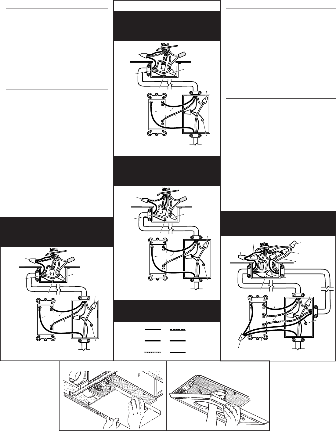
MODEL / MODELO 164
Light & Vent operate together -
Heat separately
La luz y el ventilador funcionan a la vez -
Calentador por separado
HEAT
CALEFACCION
120 VAC LINE IN
LINEA DE ENTRADA 120 VCA
GROUND
TIERRA
3 BLACK WIRES
3 ALAMBRES NEGROS
3 WHITE WIRES
3 ALAMBRES
BLANCOS
LIGHT
LUZ
BLACK
NEGRO
3-FUNCTION CONTROL
CONTROLE DE 3 FUNCCIONES
WHITE to WHITE / GRAY
BLANCO a BLANCO / GRIS
VENT
EXTRACCION
BLACK to BLACK
NEGRO a NEGRO
BLACK to YELLOW
NEGRO a AMARILLO
RED to RED / ROJO a ROJO
RED/ROJO
GROUND / TIERRA
WHITE to WHITE
BLANCO a BLANCO
RED to BLUE
ROJO a AZUL
MODEL / MODELO 164
Light, Vent & Heat operate separately
La luz, ventilador y calentador funcionan por
separado
FIG. 7
FIG. 8


Find Your Products By Category
Please Login
