
0
Owner's of the RCA Radio Antenna ANT3038XR gave it a score of 0 out of 5. Here's how the scores stacked up:
4
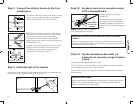
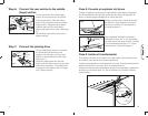
On the open end of the middle (large)
section, remove the rear nut and screw.
Find the rear section. Slide the narrow
boom of the rear antenna into the middle
(large) section. Tap lightly with a rubber
mallet on the end of the small boom,
aligning the holes for the screw. (See fi gure
6.)
Re-install the screw and nut; be sure to
tighten securely.
Step 6: Connect the rear section to the middle
(large) section
Rear
section
Middle
section
Screw
Nut
Fig. 6
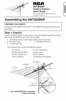
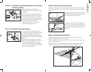
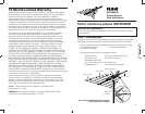
Step 7: Connect the phasing lines
On the middle (large) section, near where
the middle and rear sections come
together, fi nd the posts on the top and
bottom of the last element holder studs.
(See fi gure 7.)
Place the phasing lines from the rear
section over the studs, one on the top side
and one on the bottom. Then fasten them
to the posts with washers and #10 fl ange
nuts. Tighten securely.
Nut
Washer
Stud
Phasing
line
Fig. 7
13
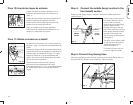
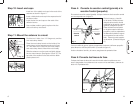
Paso 8: Conecte el sujetador del brazo
Coloque el sujetador del brazo en la parte superior de la antena. Asegúrese
que las abrazaderas del mástil (las secciones color latón) del sujetador del
brazo y la antena estén orientadas en la misma dirección.
Ubique el orifi cio para el tornillo en el brazo
del refl ector y fi je el sujetador con una de
las tuercas y tornillos #10 suministrados.
(Consulte la fi gura 8.)
T
ornillo
Tuerca
Fig. 9
Fig. 8
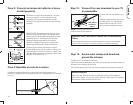
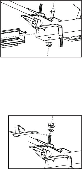
Paso 9: Instale el transformador
Encuentre la conexión del conductor en la parte inferior de la sección frontal
de la antena, justo detrás de los brazos del refl ector.
Coloque dos arandelas en cada prisionero con rosca. Coloque una tuerca #10
sobre cada prisionero con rosca, pero no la apriete todavía.
Coloque los extremos del transformador entre las dos arandelas y apriete bien
las tuercas. (Consulte la fi gura 10.) Fije el conductor de conexión coaxial al
transformador.
Transformador
Conexiones
del
conductor
Fig. 10
Gire el sujetador del brazo hacia abajo y
hacia atrás. Forme una “V” con las bandas
de metal. Utilice una de las tuercas y tornillos
#10 suministrados para fi jar la “V” a cada
lado del brazo. (Consulte la fi gura 9.)
Español


Find Your Products By Category
Please Login
