

0
Owner's of the DeWalt Lawn Mower Accessory DWE315K gave it a score of 0 out of 5. Here's how the scores stacked up:

ENGLISH
31
CAUTION: Read and follow all
manufacturers' safety warnings for any
accessories used with this tool.
CAUTION: To avoid injury, ensure
adaptor and accessory are securely
tightened.
Non-D
EWALT accessories can be attached using
the universal adaptor.
1. Place the washer (k) on the tool.
2. Place accessory on to washer.
3. Tighten and secure adaptor nut (l) using hex
wrench (p).
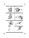
Attaching the Cut Guide (fi g. 7–12)
The depth/cut guide allows you to precisely cut
material at a specified depth and more accurately
track a marked cut line.
1. Attach the cut guide block (f) by inserting
the accessory tabs (m) on the guide into the
accessory side mount slots (e) on the main
body of the tool.
2. Secure the block to the main body with the
supplied screw (o) and washer (u). Tighten with
the supplied hex wrench (p).
DEPTH GUIDE
This feature allows you to precisely cut material at a
specified depth.
1. Insert the guide arm (g) as shown in figure 8 into
the front slot on the guide block (f).
2. Adjust the length of the guide by pulling out or
pushing inward to achieve the desired cut depth
as shown in figure 9.
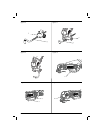
3. Secure the guide in place by turning the depth/
cut adjustment knob (n) clockwise. To release
the guide turn the depth/cut adjustment knob
counterclockwise.
CUT GUIDE
This feature allows you to more accurately track a
marked cut line.
1. Insert the guide arm (g) as shown in figure 10
into the slots on the left and right sides of the
guide block (f).
2. Adjust the length of the guide by pulling out or
pushing inward to achieve the desired length as
shown in figure 11.
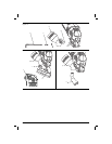
3. Secure the guide in place by turning the depth/
cut adjustment knob (n) clockwise. To release
the guide turn the depth/cut adjustment knob
counterclockwise.
NOTE: The guide arm can also be placed in the
guard assembly vertically in order to set the height
off a cut. Refer to figure 12.
Attaching the Dust Extraction
Adaptor (fi g. 16)
The Dust Extraction Adaptor allows you to connect
the tool to an external dust extractor, either using
the AirLock™ system (DWV9000-XJ), or a standard
35mm dust extractor fitment.
1. Attach the dust extraction adaptor (q) by
inserting the tabs (m) in to the accessory side
mount slots (e).
2. Insert screw (o) and washer (u) into the dust
extraction adaptor (q) and tighten with the
supplied hex key (p).
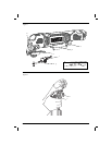
OPERATION
Instructions for Use (fi g. 13, 14)
WARNING: Always observe the safety
instructions and applicable regulations.
WARNING: To reduce the risk
of serious personal injury, turn
tool off and disconnect tool from
power source before making any
adjustments or removing/installing
attachments or accessories.
WARNING: Ensure switch is fully OFF
before plugging in the power cord.
1. Plug in power cord.
2. To turn the tool ON, hold it as shown in
figure13 and press the variable speed
trigger(a).
NOTE: The further the trigger switch is
depressed the faster the tool will operate.
If in doubt about the proper speed for your
operation, test the performance at low speed
and gradually increase until a comfortable speed
is found.
3. To turn the tool OFF, release the variable speed
trigger (a).
Lock-on Button (fi g. 14)
For more comfort in extended use applications, the
lock-on button (d) can lock the trigger trigger (a) in
the depressed position.
LED Worklight (fi g. 15)
The LED worklight (b) will activate when the trigger
is depressed.


Find Your Products By Category
Please Login
