
0
Owner's of the Black & Decker Impact Driver Black & Decker Cordless Impact Driver gave it a score of 0 out of 5. Here's how the scores stacked up:
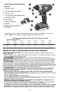
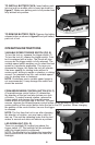
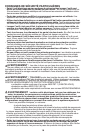
TO INSTALL BATTERY PACK: Insert battery pack
into tool until an audible click is heard as shown in
figure C. Make sure battery pack is fully seated and
fully latched into position.
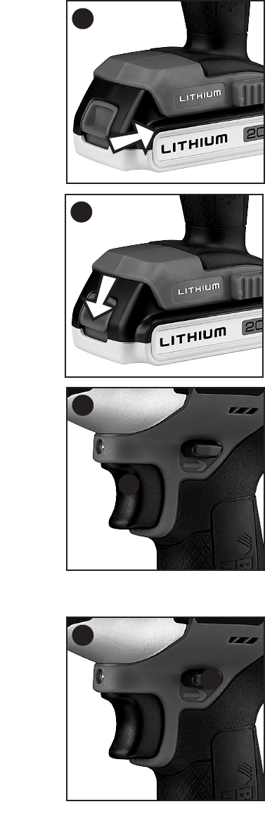
TO REMOVE BATTERY PACK: Depress the battery
release button as shown in figure D and pull battery
pack out of tool.
OPERATING INSTRUCTIONS
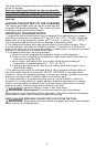
VARIABLE SPEED TRIGGER SWITCH (FIG. E)
To turn the tool on, squeeze the trigger switch (1).
To turn the tool off, release the trigger switch. Your
tool is equipped with a brake. The chuck will stop
as soon as the trigger switch is fully released. The
variable speed switch enables you to select the best
speed for a particular application. The more you
squeeze the trigger, the faster the tool will operate.
Use lower speeds for starting holes without a
center punch, drilling in metals or plastics, or driving
screws. For maximum tool life, use variable speed
only for starting holes or fasteners.
NOTE: Continuous use in variable speed range is
not recommended. It may damage the switch and
should be avoided.
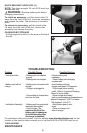
FORWARD/REVERSE CONTROL BUTTON (FIG. F)
A forward/reverse control button (2) determines
the direction of the tool and also serves as a lock
off button. To select forward rotation, release the
trigger switch and depress the forward/reverse
control button on the right side of the tool. To select
reverse, depress the forward/reverse control button on the left side of the tool. The
center position of the control button locks the tool in the OFF position. When changing
the position of the control button, be sure the trigger
is released.
NOTE: The first time the tool is run after changing
the direction of rotation, you may hear a click on
start up. This and the impacting noise that the tool
makes is normal and does not indicate a problem.
LED WORKLIGHT (FIG. G)
There is a worklight (5) located just above the
trigger switch (A). The worklight will be activated
when the trigger switch is squeezed.
NOTE: The worklight is for lighting the immediate
work surface and is not intended to be used as a
flashlight.
8
E
1
F
2
C
D


Find Your Products By Category
Please Login
