

0
Owner's of the DeWalt Saw Dewalt Next Gen Circular Saw Kit gave it a score of 0 out of 5. Here's how the scores stacked up:
9
English
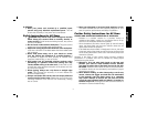
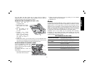
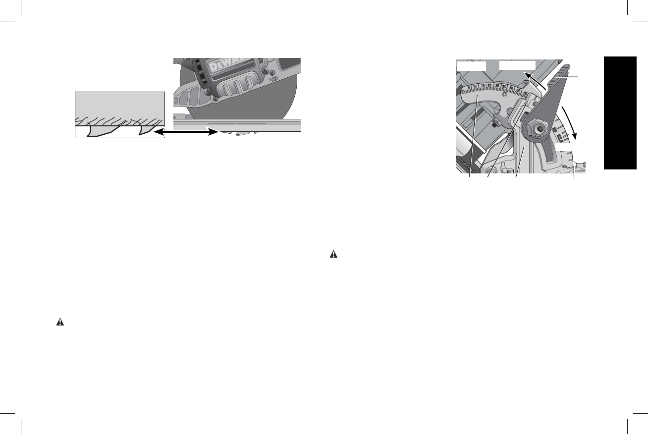
FIG. 8
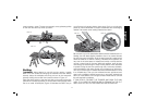
3. For the most efficient cutting action using a carbide tipped saw
blade, set the depth adjustment so that about one half of a tooth
projects below the surface of the wood to be cut.
4. A method of checking for the correct cutting depth is shown in
Figure 8. Lay a piece of the material you plan to cut along the side
of the blade, as shown in the figure, and observe how much tooth
projects beyond the material.
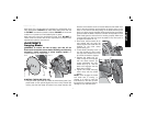
ADJUSTING DEPTH ADJUSTMENT LEVER (FIG. 7)
It may be desirable to adjust the depth adjustment lever (P). It may
loosen in time and hit the foot plate before tighten ing.
To tighten the lever, follow the steps below.
1. Hold depth adjustment lever (P) and loosen the locknut (S).
2. Adjust the depth adjustment lever by rotating it in the desired
direction about 1/8 of a revolution.
3. Retighten nut.
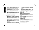
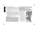
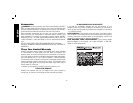
Bevel Angle Adjustment (Fig. 9)
WARNING: To reduce the risk of injury, turn unit off and
disconnect it from power source before installing and removing
accessories, before adjusting or when making repairs. An
accidental start-up can cause injury.
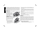
On the front of the saw is a bevel angle adjustment mechanism (G)
which consists of an angle quadrant with a pointer (T) and a bevel
adjustment lever (F). The angle
F
G
TIGHTEN
LOOSEN
T
U
V
FIG. 9
quadrant allows for coarse
adjustment. To achieve better
accuracy in cutting, use the fine
adjustment markings located
on the pivot bracket (U). The full
range of bevel adjustment is 0
to 57 degrees. The pivot
bracket is graduated in
increments of 1degree.
1. To set the saw for a
bevel cut, raise the
bevel adjustment lever
(F) to loosen the bevel
adjustment.
2. Tilt the foot plate to the desired angle by aligning the pointer (T)
with the desired angle mark on the pivot bracket (U).
3. Retighten the bevel adjustment by lowering the lever.
Bevel Detent (Fig.9)
WARNING: To reduce the risk of injury, turn unit off and
disconnect it from power source before installing and removing
accessories, before adjusting or when making repairs. An
accidental start-up can cause injury.
The DWE575 and DWE575SB are equipped with a bevel detent
feature. As you tilt the foot plate you will hear a click and feel the foot
plate stop at both 22.5 and 45 degrees. If either of these is the desired
angle, retighten the lever (F) by lowering it. If you desire another angle,
continue tilting the foot plate until the coarse bevel pointer (V) or the
fine pointer (T) aligns with the desired mark.


Find Your Products By Category
Please Login
