

0
Owner's of the Black & Decker Trimmer SF-080 gave it a score of 0 out of 5. Here's how the scores stacked up:

6
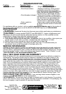
FUNCTIONAL DESCRIPTION (FIGURE A)
1. On/Off Trigger Switch 4. Auxiliary Handle 7. Trimmer Head
2. Handle 5. Height Adjust Locking Clamp 8. Edge Guide Wheel
3. Power Cord Plug 6. Trimmer Guard 9. Spool Housing
ASSEMBLY
ASSEMBLY TOOLS REQUIRED (NOT SUPPLIED): Phillips Screwdriver
WARNING:
UNPLUG THE TOOL BEFORE ATTEMPTING TO ATTACH THE GUARD.
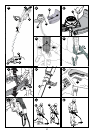
ATTACHING THE GUARD (FIGURES B, C)
WARNING: NEVER OPERATE TOOL WITHOUT GUARD FIRMLY IN PLACE. The
guard must always be properly attached on the tool to protect the user.
• Removethescrewfromtheguard.
• Keepingtheguardsquaretothetrimmerheadslideitintoplaceuntiltheretainingtabclicks
into place (Ensure that the guide rails (B1) on the guard (B2) are correctly aligned with the
guide rails (B3) on the trimmer head (B4) (figure B).
• Securetheguardwiththescrew(C1) (figure C).
ATTACHING THE AUXILIARY HANDLE (FIGURES D, E)
• Toattachthehandle,pressinonthebuttons(D1) on both sides of the upper housing as
shown in figure D.
•
Position the handle as shown in figure E(withtheBlack&Deckerlogofacingupward).Partially
push the handle on so that it will hold the buttons in when you release them with your hand.
• Pushthehandlecompletelyontothehousingandpositionitslightlyuntilit“snaps”into
place (figure E).
•
To adjust the handle up or down, press in on the button (F1) and raise or lower the handle.
• Thehandleshouldbeadjustedsothatyourfrontarmisstraightwhenthetrimmerisinthe
working position.
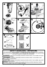
ADJUSTING THE HEIGHT OF THE TOOL (FIGURE G)
This tool has a telescopic mechanism, allowing you to set it to a comfortable height.
To adjust the height setting:
• Releasetheheightadjustlockingclamp(G1).
• Gentlypullthetube(G2) up or down to the desired height.
• Closetheheightadjustlockingclamp(G1).
OPERATION
WARNING: Always use proper eye protection that conforms to ANSI Z87.1 (CAN/CSA
Z94.3) while operating this power tool.
WARNING: Disconnect the plug from the power source before making any assembly,
adjustments or changing accessories. Such preventive safety measures reduce the risk of
starting the tool accidentally.
CAUTION: Beforeyoubegintrimming,onlyusetheappropriatetypeofcuttingline.
CAUTION: Inspect area to be trimmed and remove any wire, cord, or string-like objects
which could become entangled in the rotatinglineorspool.Beparticularlycarefultoavoidany
wire which might be bent outwardly into the path of the tool, such as barbs at the base of a
chain link fence.
SWITCHING ON AND OFF (FIGURE H)
WARNING: Never attempt to lock the trigger switch in the on position.
• Toturnthetoolon,squeezethetriggerswitch(H1)
• Toturnthetooloff,releasethetriggerswitch(H1).
EXTENSION COrd rETaINEr (fIgurE I)
WARNING: Ensure the trigger switch is not engaged to reduce the risk of starting the
tool accidentally.
A cord retainer is incorporated into the rear of the handle on the power head.
• Tousethecordretainerasshownin figure I, feed the extension cord into the cord retainer
housing (I1). Loop the extension cord around the cord retainer (I2) so it rests in the cord
retainer. Then plug the extension cord into the power head.


Find Your Products By Category
Please Login
