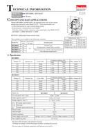

0
Owner's of the Makita Router electronic router gave it a score of 0 out of 5. Here's how the scores stacked up:
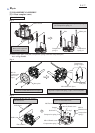
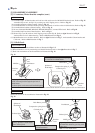
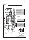
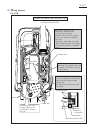
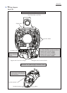
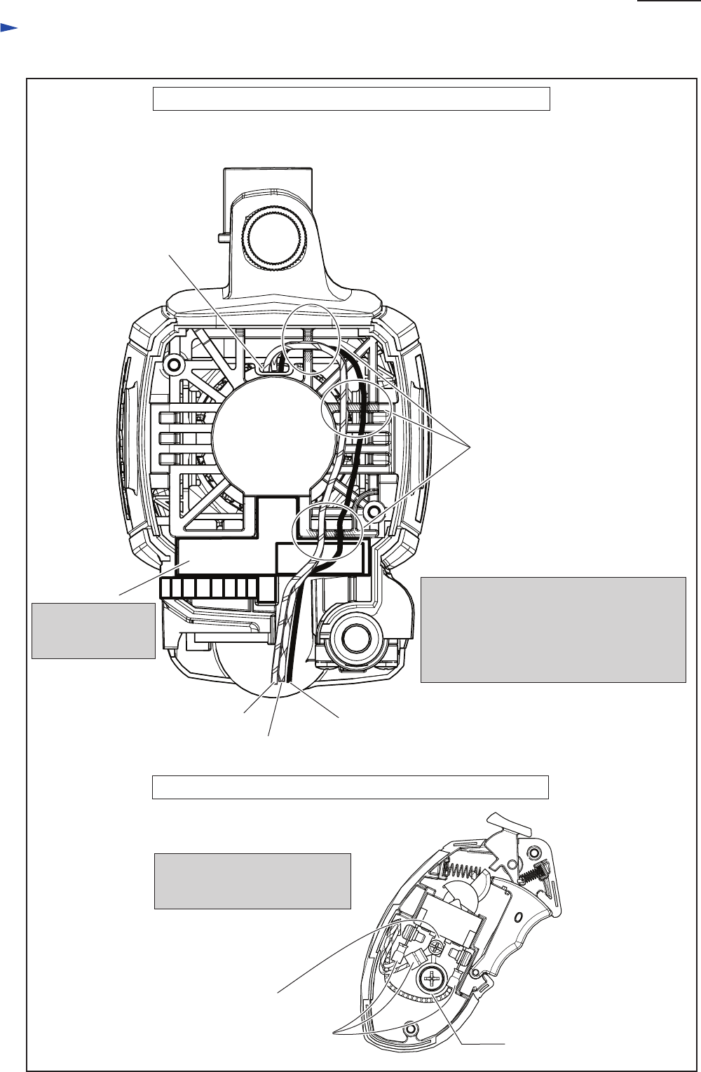
Wiring diagram
RP2301FC with electric Brake, LED Job Light, Electronic Control
Fig. D-3A
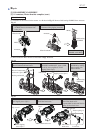
Lead wire holder
Wiring in Motor housing
on top side (Rear cover side)
Wiring in Grip (R)
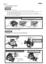
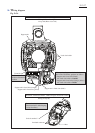
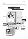
Support unit
When putting Support unit’s Lead wires
into Lead wire holders, put them as follows.
* Support unit’s Lead wire (black)
into Lead wire holder of outside
* Support unit’s Lead wires (orange, yellow)
into Lead wire holder of inside
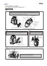
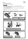
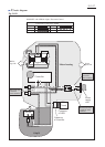
Controller
Support unit’s Lead wire (orange)
Support unit’s Lead wire (black)
Insulated connector
Connect Insulated connector to
Switch terminal 2 while keeping
it away from Boss.
Support unit’s Lead wire (yellow)
Put Controller into
the above illustrated
position.
Switch terminal 2
RP2301FC with electric Brake, LED Job Light, Electronic Control
Insulated Terminal
Boss
P 12/ 27


Find Your Products By Category
Please Login
