
0
Owner's of the Makita Router electronic router gave it a score of 0 out of 5. Here's how the scores stacked up:
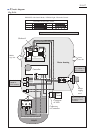
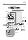
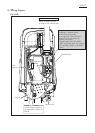
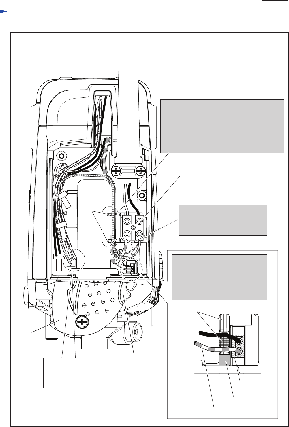
Wiring diagram
P 17/ 27
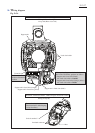
R1801F with electric Brake, LED Job Light
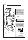
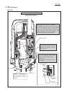
Grip R
Lead wire
holder
When putting Lead wires for connecting
to Terminal block, into this Lead wire holder,
thin Lead wire (purple) of Power supply circuit
has to be put under the following Lead wires.
* Thick Lead wire (red) of Power supply circuit
* Thick Connecting lead wire (purple) for
connecting Switch to Terminal block
Switch lever
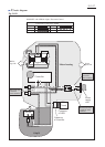
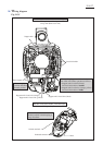
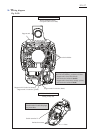
The extra portion of Controller’s
thin Lead wires (black, red) to be
connected to LED has to be put
in this position.
Connector of Controller’s lead wires
has to be connected to LED circuit,
facing Lead wire (Red) to Red
marking side.
And put the Lead wires into Lead
wire holder.
Terminal block
Lead wire holder
Connector of
controller
Red marking
Controller’s Lead wire (red)
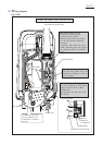
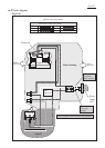
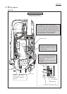
Wiring in Motor housing
on Grip R side (Switch side)
Connecting lead wires
(yellow, orange purple) to
be connected to Switch in
Grip R
Fig. D-2C


Find Your Products By Category
Please Login
